 ←Index
by Professor Petabyte
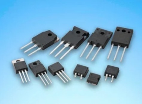
A MOSFET (Metal-Oxide-Semiconductor Field-Effect Transistor) is a semiconductor device that acts as an electronic switch or amplifier. It controls the flow of current between two terminals (source and drain) by applying a voltage to a third terminal (gate). Essentially, it regulates current flow based on voltage input, making it fundamental in digital and analog circuits.
The main difference is that a BJT (Bipolar Junction Transistor) is a current-controlled device, while a MOSFET (Metal-Oxide-Semiconductor Field-Effect Transistor) is a voltage-controlled device. BJTs use base current to control collector-emitter current, whereas MOSFETs use gate voltage to control drain-source current. Key differences also include their terminal names (base/collector/emitter for BJT, gate/drain/source for MOSFET), efficiency, and primary applications.
The transistor was invented in 1947 by John Bardeen, Walter Brattain, and William Shockley at Bell Labs to replace bulky vacuum tubes, with the initial device being a point-contact transistor made of germanium. Their work, which earned them the 1956 Nobel Prize in Physics, led to the development of the more practical bipolar junction transistor by Shockley in 1948 and later the widely used silicon MOSFET. This groundbreaking invention revolutionized electronics by enabling miniaturization, reduced power consumption, and paved the way for modern computers and electronics
There are two main types:
| Type | Symbol | Conducts when | Common Use |
|---|---|---|---|
| N-channel | N-MOS | Gate voltage > Source | Low-side switching |
| P-channel | P-MOS | Gate voltage < Source | High-side switching |
Using NPN and PNP MOSFETs is a bit of a misnomer — MOSFETs are not categorized as NPN/PNP, which are bipolar junction transistor (BJT) types. Instead, MOSFETs come in two polarities:
The following information focuses on how to use N-channel and P-channel MOSFET.
| Feature | N-Channel MOSFET | P-Channel MOSFET |
|---|---|---|
| Turns ON when... | Gate voltage is higher than Source (typically by 2-4V) | Gate voltage is lower than Source (typically by 2-4V) |
| Common Switching Use | Low-side switching (between load and GND) | High-side switching (between +V and load) |
| Gate Drive Requirement | Needs gate pulled high to turn ON | Needs gate pulled low to turn ON |
| Preferred For | Efficiency, speed, cost, availability | Simpler high-side switch (but less efficient) |
| On-resistance (RDSon) | Typically lower | Typically higher |
| Availability | Widely available and cheaper | Less common, especially logic-level types |
| Control from MCU (5V logic) | Direct drive (if logic-level N-FET) | Possible, but only if Source is ≤5V and P-FET is logic-level |
| Internal body diode | Conducts from Drain to Source | Conducts from Source to Drain |
Common use: Switching the negative/ground side of a load.
Example: LED control from microcontroller

Gate-Source Voltage (VGS) must be above the threshold (typically 2-4V for logic-level MOSFETs).
Common use: Switching the positive side of a load.
Example:

VGS must be negative enough to turn the MOSFET on (e.g., -4V). That means Gate needs to be pulled close to GND while Source is at +5V.
| Use Case | Recommended Part |
|---|---|
| N-Channel (logic level) | IRLZ44N, IRL540N |
| P-Channel (logic level) | IRF9540N, IRF4905 |
This is one of those fundamental but crucial electronics concepts....
A MOSFET switch is often used to control power to a load (motor, LED, circuit board, etc.).
The difference comes down to where you place the MOSFET relative to the load and the supply rails.
| Task | Use N-Channel | Use P-Channel |
|---|---|---|
| Switching ground (low-side) | Yes | Rarely |
| Switching +V (high-side) | Needs driver | Yes |
| Logic level control (3.3-5V) | Logic N-FET | Logic P-FET (less common) |
| Feature | N-Channel MOSFET | P-Channel MOSFET |
|---|---|---|
| Turns ON when... | Gate voltage is higher than Source (typically by 2-4V) | Gate voltage is lower than Source (typically by 2-4V) |
| Common Switching Use | Low-side switching (between load and GND) | High-side switching (between +V and load) |
| Gate Drive Requirement | Needs gate pulled high to turn ON | Needs gate pulled low to turn ON |
| Preferred For | Efficiency, speed, cost, availability | Simpler high-side switch (but less efficient) |
| On-resistance (RDSon) | Typically lower | Typically higher |
| Availability | Widely available and cheaper | Less common, especially logic-level types |
| Control from MCU (5V logic) | Direct drive (if logic-level N-FET) | Possible, but only if Source is ≤5V and P-FET is logic-level |
| Internal body diode | Conducts from Drain to Source | Conducts from Source to Drain |
Yes. Here's why:
RDS(on) = "Drain-to-Source Resistance when on".
It's the effective resistance between the MOSFET's drain and source terminals when the MOSFET is fully turned on (saturated conduction mode).
Saturation mode is when a transistor is fully on, acting like a nearly ideal short circuit between its collector and emitter, with current flowing freely through it. This state is achieved by biasing the transistor's base-emitter and base-collector junctions to be forward-biased, allowing significant current to flow. Transistors are typically driven into saturation for use as switches, where a fully on state represents the "closed" position.
P = I2 x RDS(on)
Where:
Suppose a MOSFET has:-
RDS(on) = 10mΩ (or 0.01Ω) and carries 10 Amps:
P = (10)2 x 0.01 = 1W
So the MOSFET will dissipate 1 watt as heat.
If instead:-
RDS(on) = 50mΩ (or 0.05Ω) and carries 10 Amps:
P = 100 x 0.05 = 5W
That's 5 times more heat, which may require a heatsink.
RDS(on) is a key figure of merit that tells you how much resistance the MOSFET has when acting as a closed switch. The lower that resistance is, the more current you can pass with less power loss.
A MOSFET doesn't turn on like a light switch — it gradually becomes more conductive as you increase Vgs (the voltage between Gate and Source).
Take an IRLZ44N (logic-level N-channel MOSFET):
People see "Logic-Level MOSFET" and assume it works perfectly at 3.3 V.
RDS(on) shrinks as Vgs increases. To minimize heating, you need to drive the MOSFET gate with enough voltage for it to reach its lowest RDS(on).
| MOSFET | Type | P-Channel MOSFET |
|---|---|---|
| IRLZ44N | N-channel | ~0.022 Ω |
| IRF9540N | P-channel | ~0.117 Ω |
Both are common power MOSFETs in the same family. The N-channel one has ~5x lower on-resistance.